At some point I got a defective Yashica Electro 35 GT and decided to try to bring it back to life but not by repairing the original electronics but making an extensive retrofit on it by scrapping out everything and making a microcontroller based new one. It worked very well.
Why this ? Just for fun. No real or practical need, just for the challenge. The original Yashica circuit and concept is extremely functional and very well made.
 |
| Yashica Electro 35 - Dead One |
The camera was in terrible shape inside. Lots of oxidation, damaged wires and a nonfunctioning shutter solenoid. The fact is that without a working solenoid, it would be impossible to do anything else, so the first thing I needed was to fix it.
Above is the whole leaf shutter assembly. The two copper color components at the bottom are the two coils of the solenoid. On the left side we have all the gears responsible for the shutter loading and the self timer. We can also see the iris aperture lever on the first quadrant (upper right)
 |
| Yashica shutter assembly as it is shown on the service manual |
 |
| Yashica Electro 35 shutter assembly front side |
 | |
|
The back view shows again the aperture control lever on the right and the cocking gear coupling, the "thing with a little bar crossing it". During the film advance, this gear is turned and the shutter loaded by tensioning the shutter spring. At the left, we can see the shutter release lever.
This is an electromechanical shutter. The loading and the releasing are mechanical actions, but the timing is electronically controlled.
When the shutter button is pressed, a long lever moves the release lever and the spring opens the shutter blades. The shutter is released and kept open for the exposure time by the solenoid. After the proper time, the solenoid is turned off and the shutter is closed.
The wires are for the magnet, the aperture reading and the mode reading. The apertures go from 2.8 to 16, and the modes are AUTO, Flash and B.
The flash mode ignores the light meter and set the exposure to 1/30s on the original camera. The B settings just keep the shutter opened for the time that the shutter button is pressed. The auto mode is actually a semi-automatic mode called Aperture Priority when you set the aperture value and ISO (according to the film sensibility) and the camera calculates the shutter time. The original limits are between 16s and 1/500s.
Back to the solenoid, I tested it for continuity and guess what... Open circuit, meaning that the wire melted in some point inside. I decided to disassemble it and fix. Took me some time and a lot of patience. The wire is extremely thin, I suspect it's 42 AWG gauge.
 |
| Damaged Solenoid |
 |
| Where the wire was broken |
I had to make delicate soldering and wind again the wire. The two coils had the same resistence, exactly 50 ohms. The fixed solenoid is shown below. This little job cost me one day ...
 |
| Fixed Solenoid |
Now the aperture and mode module. Below, how it looks like when removed. There are two printed circuit boards. The left one with the resistors is for the aperture control and the right one for the mode control. The mode control one has a complex look but actually it's rather simple: It's a 2 pole x 3 position switch, linked to the mode dial. The aperture control is a 1 pole x 8 position switch, linked to the aperture control ring. The aperture control ring has also a mechanical coupling that is connected to the shutter assembly module directly to the aperture control lever.
 |
| Aperture and mode control module, front view |
 |
| Mode dial switch detail |
 |
| Aperture dial switch detail from below |
With the aperture control board moved, we can see the movable contact linked to the aperture coupling lever and the contacts for each aperture position under the board.
 |
| Add caption |
It works this way: At each aperture position, the contact below the board makes contact with on pad below the board. The 8 resistors are connected in series and each position gives a different resistance reading. The original resistor values were in logarithmic relation. This works exactly like a potentiometer with three terminals.
I modified this circuit and changed all the 8 resistors for 1 kohm and used just two terminals, the center tap (moving cursor) and one of the sides.
 |
| Yashica Electro 35 circuit (meter and timing control) |
 |
| Shutter Principle |
The original circuit is pretty elegant and functional. It has just five transistors, not a single one integrated circuit and it's precise enough for slide films!
But don't be fooled! The complex design of the switches makes understanding the circuit a challenge!
Let's keep things simple and just forget the original circuit. It's beyond the scope to explain how it works.
Now, some technical drawings to figure out how things are arranged.
 |
| Yashica Electro 35 exploded view - top |
 |
| Yashica Electro 35 exploded view - main body - transport |
 |
| Yashica Electro 35 exploded view - bottom - transport gears, battery compatment |
 |
| Yashica Electro 35 exploded view - objective assembly |
 |
| Yashica Electro 35 exploded view - Front plate assembly and light meter |
 |
| Yashica Electro 35 exploded view - Rangefinder assembly |
Steps
- Remove the top plate. Avoid disassembling unnecessary things.
- Remove the rangefinder (in ONE piece)
- Remove the light meter module
- Remove the front plate
- Remove the objective in one piece
- Disassemble the objective
Step 6 is complex. Think before doing. Do not disassemble the shutter/iris mechanism neither the shutter gears! You just need to remove part 317-227
You need to remove all the lens elements with the proper tools (lens spanner, rubber pads). Take notes of the lens arrangement.
DO NOT mess with the focusing mechanism parts 317-202 to 078-003, be advised! Same for the rangefinder module!
You NEED to take notes of what you're doing.
Basically, the objective is to strip ou ALL the electronic parts, change everything for a microcontroller, rewire, reassemble and recalibrate everything.
Assuming you have the front plate on hands, with the lens and shutter removed. Take a look below.
 |
| Front plate with the shutter / lens removed (front view) |
The front view shows the focus helicoid and he shutter cock rod and release lever. Let them alone !
 |
| Front plate view from behind |
The back has very important parts.
The shutter cocking action happens when the film advance lever is used. During this action, the shutter cock rod is turned and the proper gear in the shutter assembly unit is moved until the shutter spring is tensioned and the shutter locked in position.
Now take a look at the image above. The shutter button rod, when moved down, makes the L Shaft touch the shutter release lever. This lever is coupled with the shutter release on the shutter assembly unit. When the L Shaft hit the lever, the shutter is fired.
Coupled to the rod, there is a contact assembly that moves up and down and touches the contacts of a small printed circuit board with a complex contact pattern on it. Take a look at the next figure.
 |
| Switch assembly on the front plate |
Forget the left-session (in red), we won't use it. The right session (in green) is a 1 pole x 3 position switch. The cursor contact of this switch is identified as "A" and connected to VCC
- Shutter button not pressed: do nothing, contact B0 not used
- Shutter button half-pressed: make light metering, B1 = High
- Shutter button fully pressed: release shutter, B2 = High
B1 and B2 will be used as control signals for the microcontroller.
The aperture resistor string has two wires and a unique resistance value identifies the desired aperture, set on the aperture adjustment ring
The mode selection works in a similar way. I connected 3 resistors one for each mode, with different values (1K, 4.7K and 10K)
By measuring the resistance values, it's possible to know the mode and the aperture position.
At that time 2006 if I remember well, I decided to use the BASIC Stamp I microcontroller from Parallax Inc. . It was not the cheapest but it was very easy to program.
For today standards it's a dinosaur: 256 bytes of EEPROM (yes, bytes, not KB or MB) and 16 bytes of RAM, 8 digital/analog I/O ports and a VERY powerful BASIC interpreter.
It's fun to program and a challenge to squeeze the firmware in 256 bytes of memory, but it's perfectly possible. If you have one or find one at a reasonable price, it's not a so crazy idea, but for $30 is a big no-no. My tip is to use an Arduino Pro Micro.
It's fun to program and a challenge to squeeze the firmware in 256 bytes of memory, but it's perfectly possible. If you have one or find one at a reasonable price, it's not a so crazy idea, but for $30 is a big no-no. My tip is to use an Arduino Pro Micro.
The program flowchart is very simple:
 |
| Firmware flowchart |
It's in Portuguese but I'll provide a translation.
Det.Modo = Mode detection (flash, auto, bulb), by measuring a resistance value
Det.Abertura = Aperture detection, by measuring a resistance value
B1? = Is the shutter half-pressed?
Demorou muito ? = Took too long ?
Mede Luz = Make Light Measurement, by measuring a resistance value from the LDR
Calcula T = Calculate exposure time
Led Amar. = Yellow Led (turn on if T > 1/30s)
Led.Verm. = Red Led (turn on if T < 1/500s)
B2? = Test for fully pressed button. If yes keep shutter open for T seconds
That's it.
The simplified circuit:
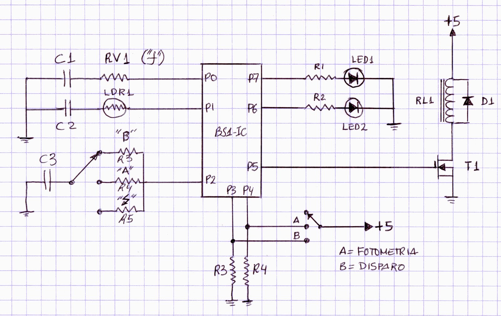 |
| New BS1-IC camera control system |
RV1 is the equivalent resistor of the aperture resistor array
LDR1 is the original light meter LDR
The switch on left is the mode switch with the 3 resistors (1K,4K7 and 10K)
The switch on the right is that one on the front plate (A=B1 and B=B2)
The original warning lamps were changed by 3mm LEDs
RL1 is the original shutter solenoid (electromagnet).
The D1 protection diode is absolutely necessary.
T1 is a P-Channel MOSFET (BS170P)
T1 is a P-Channel MOSFET (BS170P)
Like I said, I don't have the firmware code anymore, but I can tell some tips.
a) The resistance measurement is done using the PBASIC RCTIME function. Actually, RCTIME measures the RC constant of a resistor and a capacitor in series. Note the 3 capacitors C1, C2 and C3. They all have the same 0.1 uF value.
b) The output pulse width for the magnet is done using the PULSOUT function
Of course, you can use a more modern microcontroller like an Arduino or something like.
Now, some pictures of what I did.
 |
| Light meter assembly with the LDR and C2 |
 |
| Main circuit |
The parallel grey wires are for programming the MCU. The BS1-IC is the green module on the left. At the MCU top is the solenoid driver MOSFET.
 |
| First version of Solenoid driver, R3 and R4 for a clearer view. |
I also tried some other arrangements:
 |
| Basic Stamp in a different position |
Tips for Arduinos:
Again, sorry for not providing the complete project :(
- I would use an Arduino Nano for 3.3V supply and use one CR123 lithium battery
- I would use a direct LUX reading light sensor like the TSL 2561 (I2C interface)
- The aperture resistor array could be read using AnalogRead function
- The mode switch and the shutter switch could be read using DigitalRead
- Use interrupts instead of polling for trigger events
Suggestions:
- Change the mechanical ISO dial for a switch and add a small oled display at the battery check button plastic plate to show selected ISO and other data
I'm pretty sure that a more modern approach with an Arduino would be way easier to do.
No comments:
Post a Comment